
Inductors react against changes in current because of the energy stored in this magnetic field. When we construct a transformer from two inductor coils around a common iron core, we use this field to transfer energy from one coil to the other. However, there are simpler and more direct uses for electromagnetic fields than the applications we've seen with inductors and transformers. The magnetic field produced by a coil of current-carrying wire can be used to exert a mechanical force on any magnetic object, just as we can use a permanent magnet to attract magnetic objects, except that this magnet (formed by the coil) can be turned on or off by switching the current on or off through the coil.
If we place a magnetic object near such a coil for the purpose of making that object move when we energize the coil with electric current, we have what is called a solenoid. The movable magnetic object is called an armature, and most armatures can be moved with either direct current (DC) or alternating current (AC) energizing the coil. The polarity of the magnetic field is irrelevant for the purpose of attracting an iron armature. Solenoids can be used to electrically open door latches, open or shut valves, move robotic limbs, and even actuate electric switch mechanisms. However, if a solenoid is used to actuate a set of switch contacts, we have a device so useful it deserves its own name: the relay.
Relays are extremely useful when we have a need to control a large amount of current and/or voltage with a small electrical signal. The relay coil which produces the magnetic field may only consume fractions of a watt of power, while the contacts closed or opened by that magnetic field may be able to conduct hundreds of times that amount of power to a load. In effect, a relay acts as a binary (on or off) amplifier.
Just as with transistors, the relay's ability to control one electrical signal with another finds application in the construction of logic functions. This topic will be covered in greater detail in another lesson. For now, the relay's "amplifying" ability will be explored.
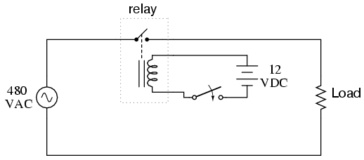
In the above schematic, the relay's coil is energized by the low-voltage (12 VDC) source, while the single-pole, single-throw (SPST) contact interrupts the high-voltage (480 VAC) circuit. It is quite likely that the current required to energize the relay coil will be hundreds of times less than the current rating of the contact. Typical relay coil currents are well below 1 amp, while typical contact ratings for industrial relays are at least 10 amps.
One relay coil/armature assembly may be used to actuate more than one set of contacts. Those contacts may be normally-open, normally-closed, or any combination of the two. As with switches, the "normal" state of a relay's contacts is that state when the coil is de-energized, just as you would find the relay sitting on a shelf, not connected to any circuit.
Relay contacts may be open-air pads of metal alloy, mercury tubes, or even magnetic reeds, just as with other types of switches. The choice of contacts in a relay depends on the same factors which dictate contact choice in other types of switches. Open-air contacts are the best for high-current applications, but their tendency to corrode and spark may cause problems in some industrial environments. Mercury and reed contacts are sparkless and won't corrode, but they tend to be limited in current-carrying capacity.
Shown here are three small relays (about two inches in height, each), installed on a panel as part of an electrical control system at a municipal water treatment plant:
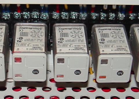
The relay units shown here are called "octal-base," because they plug into matching sockets, the electrical connections secured via eight metal pins on the relay bottom. The screw terminal connections you see in the photograph where wires connect to the relays are actually part of the socket assembly, into which each relay is plugged. This type of construction facilitates easy removal and replacement of the relay(s) in the event of failure.
Aside from the ability to allow a relatively small electric signal to switch a relatively large electric signal, relays also offer electrical isolation between coil and contact circuits. This means that the coil circuit and contact circuit(s) are electrically insulated from one another. One circuit may be DC and the other AC (such as in the example circuit shown earlier), and/or they may be at completely different voltage levels, across the connections or from connections to ground.
While relays are essentially binary devices, either being completely on or completely off, there are operating conditions where their state may be indeterminate, just as with semiconductor logic gates. In order for a relay to positively "pull in" the armature to actuate the contact(s), there must be a certain minimum amount of current through the coil. This minimum amount is called the pull-in current, and it is analogous to the minimum input voltage that a logic gate requires to guarantee a "high" state (typically 2 Volts for TTL, 3.5 Volts for CMOS). Once the armature is pulled closer to the coil's center, however, it takes less magnetic field flux (less coil current) to hold it there. Therefore, the coil current must drop below a value significantly lower than the pull-in current before the armature "drops out" to its spring-loaded position and the contacts resume their normal state. This current level is called the drop-out current, and it is analogous to the maximum input voltage that a logic gate input will allow to guarantee a "low" state (typically 0.8 Volts for TTL, 1.5 Volts for CMOS).
The hysteresis, or difference between pull-in and drop-out currents, results in operation that is similar to a Schmitt trigger logic gate. Pull-in and drop-out currents (and voltages) vary widely from relay to relay, and are specified by the manufacturer.
- REVIEW:
- A solenoid is a device that produces mechanical motion from the energization of an electromagnet coil. The movable portion of a solenoid is called an armature.
- A relay is a solenoid set up to actuate switch contacts when its coil is energized.
- Pull-in current is the minimum amount of coil current needed to actuate a solenoid or relay from its "normal" (de-energized) position.
- Drop-out current is the maximum coil current below which an energized relay will return to its "normal" state.
Time-delay relays
Time-delay relay contacts must be specified not only as either normally-open or normally-closed, but whether the delay operates in the direction of closing or in the direction of opening. The following is a description of the four basic types of time-delay relay contacts.
First we have the normally-open, timed-closed (NOTC) contact. This type of contact is normally open when the coil is unpowered (de-energized). The contact is closed by the application of power to the relay coil, but only after the coil has been continuously powered for the specified amount of time. In other words, the direction of the contact's motion (either to close or to open) is identical to a regular NO contact, but there is a delay in closing direction. Because the delay occurs in the direction of coil energization, this type of contact is alternatively known as a normally-open, on-delay:

The following is a timing diagram of this relay contact's operation:

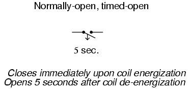
Next we have the normally-open, timed-open (NOTO) contact. Like the NOTC contact, this type of contact is normally open when the coil is unpowered (de-energized), and closed by the application of power to the relay coil. However, unlike the NOTC contact, the timing action occurs upon de-energization of the coil rather than upon energization. Because the delay occurs in the direction of coil de-energization, this type of contact is alternatively known as a normally-open, off-delay:
The following is a timing diagram of this relay contact's operation:

Next we have the normally-closed, timed-open (NCTO) contact. This type of contact is normally closed when the coil is unpowered (de-energized). The contact is opened with the application of power to the relay coil, but only after the coil has been continuously powered for the specified amount of time. In other words, the direction of the contact's motion (either to close or to open) is identical to a regular NC contact, but there is a delay in the opening direction. Because the delay occurs in the direction of coil energization, this type of contact is alternatively known as a normally-closed, on-delay:

The following is a timing diagram of this relay contact's operation:

Finally we have the normally-closed, timed-closed (NCTC) contact. Like the NCTO contact, this type of contact is normally closed when the coil is unpowered (de-energized), and opened by the application of power to the relay coil. However, unlike the NCTO contact, the timing action occurs upon de-energization of the coil rather than upon energization. Because the delay occurs in the direction of coil de-energization, this type of contact is alternatively known as a normally-closed, off-delay:

The following is a timing diagram of this relay contact's operation:

Time-delay relays are very important for use in industrial control logic circuits. Some examples of their use include:
- Flashing light control (time on, time off): two time-delay relays are used in conjunction with one another to provide a constant-frequency on/off pulsing of contacts for sending intermittent power to a lamp.
- Engine autostart control: Engines that are used to power emergency generators are often equipped with "autostart" controls that allow for automatic start-up if the main electric power fails. To properly start a large engine, certain auxiliary devices must be started first and allowed some brief time to stabilize (fuel pumps, pre-lubrication oil pumps) before the engine's starter motor is energized. Time-delay relays help sequence these events for proper start-up of the engine.
- Furnace safety purge control: Before a combustion-type furnace can be safely lit, the air fan must be run for a specified amount of time to "purge" the furnace chamber of any potentially flammable or explosive vapors. A time-delay relay provides the furnace control logic with this necessary time element.
- Motor soft-start delay control: Instead of starting large electric motors by switching full power from a dead stop condition, reduced voltage can be switched for a "softer" start and less inrush current. After a prescribed time delay (provided by a time-delay relay), full power is applied.
- Conveyor belt sequence delay: when multiple conveyor belts are arranged to transport material, the conveyor belts must be started in reverse sequence (the last one first and the first one last) so that material doesn't get piled on to a stopped or slow-moving conveyor. In order to get large belts up to full speed, some time may be needed (especially if soft-start motor controls are used). For this reason, there is usually a time-delay circuit arranged on each conveyor to give it adequate time to attain full belt speed before the next conveyor belt feeding it is started.


The "watchdog" timer is especially useful for monitoring of computer systems. If a computer is being used to control a critical process, it is usually recommended to have an automatic alarm to detect computer "lockup" (an abnormal halting of program execution due to any number of causes). An easy way to set up such a monitoring system is to have the computer regularly energize and de-energize the coil of a watchdog timer relay (similar to the output of the "recycle" timer). If the computer execution halts for any reason, the signal it outputs to the watchdog relay coil will stop cycling and freeze in one or the other state. A short time thereafter, the watchdog relay will "time out" and signal a problem.
- REVIEW:
- Time delay relays are built in these four basic modes of contact operation:
- 1: Normally-open, timed-closed. Abbreviated "NOTC", these relays open immediately upon coil de-energization and close only if the coil is continuously energized for the time duration period. Also called normally-open, on-delay relays.
- 2: Normally-open, timed-open. Abbreviated "NOTO", these relays close immediately upon coil energization and open after the coil has been de-energized for the time duration period. Also called normally-open, off delay relays.
- 3: Normally-closed, timed-open. Abbreviated "NCTO", these relays close immediately upon coil de-energization and open only if the coil is continuously energized for the time duration period. Also called normally-closed, on-delay relays.
- 4: Normally-closed, timed-closed. Abbreviated "NCTC", these relays open immediately upon coil energization and close after the coil has been de-energized for the time duration period. Also called normally-closed, off delay relays.
- One-shot timers provide a single contact pulse of specified duration for each coil energization (transition from coil off to coil on).
- Recycle timers provide a repeating sequence of on-off contact pulses as long as the coil is maintained in an energized state.
- Watchdog timers actuate their contacts only if the coil fails to be continuously sequenced on and off (energized and de-energized) at a minimum frequency.